Hey guys,
I am wanting to come up with a circuit template that can be used for any new propeller projects in the future. It seems that the propeller schematics out there are incorrect and out dated. It also seemed there was a lot of misc. info floating around on the best practices to use, and I want to incorporate it all into my diagram.
This diagram is basically something that every circuit schematic/design should start out with if its containing a propeller microchip. (That is my goal)
The main things that will most likely be different on a case by case basis are how the power rails are set up. Some people might need more/less amperage, some people might want to use a switching buck/booster regulator versus a linear regulator. I included how you might set up 2x examples below.
Here is what I have so far and I would appreciate any input. If something should be changed please let me know along with the reason and I will update the diagrams:
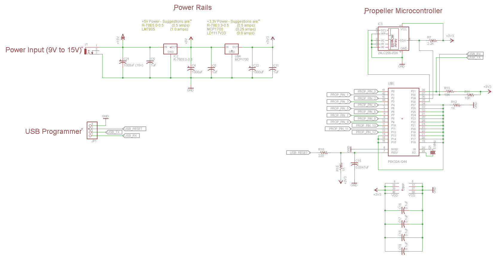
If you need +5v and +3.3v power rails:
![propeller_5v_1.jpg]()
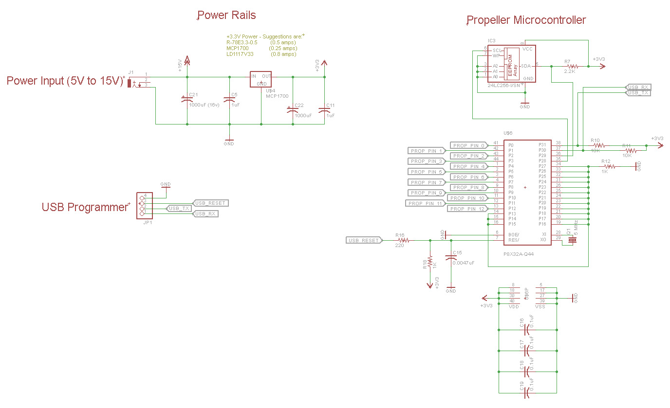
If you need only +3.3 power rail:
![propeller_3v3v_1.jpg]()
* SDA on EEPROM Pull-Up: From what I have seen on the propeller documentation, and in the datasheet for the "24LC256-I/SN", this should be a 2K or a 2.2K resistor (pull-up to 3.3 volts).
* USB RX & TX Pull-Up: Both of these lines should be pulled up so they are not floating when USB is disconnected. This will help with EMF/EMI problems as well. 10K standard pull-up resistor.
* Reset: The USB reset comming from the programmer should go through a 220 ohm resistor before connecting to the reset pin on the propeller. Even though I have heard that the propeller reset pin has an internal pull-up resistor, from my own personal experience this does not seem to be the case. I have experienced random reset problems in the past due to EMF/EMI problems and a pull-up resistor solved it. For this reason a more stronger 1k pull-up resistor paired with a small capacitor (0.0047 uF) capacitor should be standard on every design.
* Unused Propeller I/O pins: I have heard that unused propeller pins should be set as inputs (they are set to inputs by default at program start anyways) and they should not be floating... instead they should be pulled either high or low. I have them all connected together and then pulled low. I have heard that each pin should have its own separate pull-down resistor, but this seemed a bit ridiculous as it would add so many extra components to the board. The reason for pulling down unused I/O pins is for EMF/EMI protection.
Questions:
* Bulk power capacitors: The propeller documentation states to use 1000uF bulk capacitors on every power rail. I have had a few designs where space would not allow for such a large capacitor so I used a 220uF instead... and everything worked out fine. 1000uF capacitors are also more expensive if they are unnecessary. How do we determine what kind of bulk capacitor we need to be using with our design? Also, what bulk capacitor should be used with a bare bones propeller circuit?
* Does anything need to be done to the circuit in the event of the USB Programmer being plugged/unplugged while powered on or off? Or will my current diagram suffice?
Thanks and any help is greatly appreciated!
I am wanting to come up with a circuit template that can be used for any new propeller projects in the future. It seems that the propeller schematics out there are incorrect and out dated. It also seemed there was a lot of misc. info floating around on the best practices to use, and I want to incorporate it all into my diagram.
This diagram is basically something that every circuit schematic/design should start out with if its containing a propeller microchip. (That is my goal)
The main things that will most likely be different on a case by case basis are how the power rails are set up. Some people might need more/less amperage, some people might want to use a switching buck/booster regulator versus a linear regulator. I included how you might set up 2x examples below.
Here is what I have so far and I would appreciate any input. If something should be changed please let me know along with the reason and I will update the diagrams:
If you need +5v and +3.3v power rails:
If you need only +3.3 power rail:
* SDA on EEPROM Pull-Up: From what I have seen on the propeller documentation, and in the datasheet for the "24LC256-I/SN", this should be a 2K or a 2.2K resistor (pull-up to 3.3 volts).
* USB RX & TX Pull-Up: Both of these lines should be pulled up so they are not floating when USB is disconnected. This will help with EMF/EMI problems as well. 10K standard pull-up resistor.
* Reset: The USB reset comming from the programmer should go through a 220 ohm resistor before connecting to the reset pin on the propeller. Even though I have heard that the propeller reset pin has an internal pull-up resistor, from my own personal experience this does not seem to be the case. I have experienced random reset problems in the past due to EMF/EMI problems and a pull-up resistor solved it. For this reason a more stronger 1k pull-up resistor paired with a small capacitor (0.0047 uF) capacitor should be standard on every design.
* Unused Propeller I/O pins: I have heard that unused propeller pins should be set as inputs (they are set to inputs by default at program start anyways) and they should not be floating... instead they should be pulled either high or low. I have them all connected together and then pulled low. I have heard that each pin should have its own separate pull-down resistor, but this seemed a bit ridiculous as it would add so many extra components to the board. The reason for pulling down unused I/O pins is for EMF/EMI protection.
Questions:
* Bulk power capacitors: The propeller documentation states to use 1000uF bulk capacitors on every power rail. I have had a few designs where space would not allow for such a large capacitor so I used a 220uF instead... and everything worked out fine. 1000uF capacitors are also more expensive if they are unnecessary. How do we determine what kind of bulk capacitor we need to be using with our design? Also, what bulk capacitor should be used with a bare bones propeller circuit?
* Does anything need to be done to the circuit in the event of the USB Programmer being plugged/unplugged while powered on or off? Or will my current diagram suffice?
Thanks and any help is greatly appreciated!